






























![[Laser cut and engrave] Creating a test grid - Réaliser une grille de test](https://image-res.xtool.com/ali-res/community/making/fd96d829-2c42-4a8e-8d32-4e9535b9ae8d/grille.jpg?x-oss-process=image/resize,w_1200,h_900,limit_0/interlace,1/format,webp/auto-orient,1)
![[Laser cut and engrave] Creating a test grid - Réaliser une grille de test](data:image/png;base64,iVBORw0KGgoAAAANSUhEUgAAAAoAAAAKCAYAAACNMs+9AAAAAXNSR0IArs4c6QAAABdJREFUKFNjZCASMBKpjmFUId6QIjp4AAppAAuXjCs4AAAAAElFTkSuQmCC)
![[Laser cut and engrave] Creating a test grid - Réaliser une grille de test](https://image-res.xtool.com/ali-res/community/making/fd96d829-2c42-4a8e-8d32-4e9535b9ae8d/grille.jpg?x-oss-process=image/resize,w_200,h_150,limit_0/interlace,1/format,webp/auto-orient,1)
![[Laser cut and engrave] Creating a test grid - Réaliser une grille de test](https://image-res.xtool.com/ali-res/community/making/d03d34fe-594d-4a37-b87e-2416197c8f84/grille.jpg?x-oss-process=image/resize,w_200,h_150,limit_0/interlace,1/format,webp/auto-orient,1)
Creating a test grid - Réaliser une grille de test
 Instruction


Information
      These instructions may seem straightforward. That said, for people like me who are just starting out in laser engraving and cutting, it's very useful to know how to make a test grid, so as not to work blindly. And even with experience, when you change brands of material, you may have to review all your parameters.
***************************************************
Ce mode d'emploi peut paraitre simple. Cela dit pour les gens qui débutent dans la gravure et découpe laser, comme moi, il est très intéressant de savoir faire une grille de test afin de ne pas travailler à l'aveugle.
Et même avec de l'expérience, en changeant de marque de matériau on peut être obligé de revoir tous ses paramètres.
Instruction
Step1: Préparation de la grille dans XCS

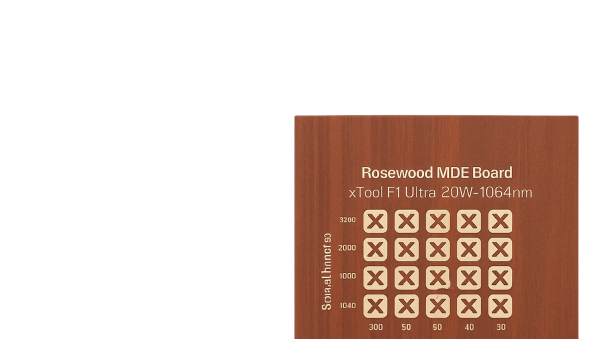
The aim of this short tutorial is to explain how to create a test grid with XCS. It's quick and easy, as xTool has integrated this function into its software.
To begin, draw a small shape of your choice, the size of which is appropriate for your surface. 4x4 mm for me.
Enter the scoring, engraving or cutting parameter, depending on what you want to test.
Here I've put in passes because I've changed wood species and yesterday's results weren't what I expected. So before wasting any more material, I thought it would be wise to do a test. I'll explain the process, because not everyone knows how to do it, and it's a shame to miss out.
***********************************************************
Ce petit tutoriel vise à vous expliquer comment réaliser une grille de test avec XCS. Cela est très facile et rapide car xTool a intégré cette fonction dans son logiciel
Pour commencer tracez une petite forme de votre choix de dimension en rapport avec votre support. 4x4 mm pour moi.
Entrez le paramètre de scoring, engraving or cutting selon ce que vous voulez tester.
Ici j'ai mis passes car j'ai changé d'essence de bois et mes résultats d'hier n'ont pas été ceux attendus. Alors avant de gâcher plus de matériel je me suis dis qu'il serait sage de faire un test. J'explique la démarche car tout le monde ne sait pas comment faire et c'est dommage de passer à côté.
Step2
Once you've traced this little square, simply click on "deploy" at the top of the page, then choose the "test array" command. It's easy - there's a test grid image next to it, so you can't miss it.
A window opens and you can set the power and speed range to be tested. You can also choose the number of rows and columns;
Don't forget to select the number of lines per cm. You can make a grid for different values, which is very instructive.
Then don't forget to set the text parameters. For simplicity, define one layer for the text and another for the grid.
You can add text elements to specify the number of lines or the type of wood....
This also applies to engraving tests.
I hope you find these explanations useful.
****************************************************
Après avoir tracé ce petit carré, il suffit de cliquer en haut sur déploiement puis de choisir la commande matériel test array. c'est facile il y a une image de grille de test à coté, vous ne pouvez pas la louper.
Une fenêtre s'ouvre et vous pouvez paramétrer la plage de puissance et de vitesse à tester. Vous pouvez également choisir le nombre de lignes et colonnes.
N'oubliez pas de sélectionner le nombre de ligne par cm. Vous pouvez faire une grille pour différente valeurs, c'est très instructifs.
Ensuite pensez à bien paramétrer le texte. Pour plus de simplicité définissez un calque pour le texte et un autre pour la grille.
Vous pouvez ajouter des élément de texte afin de préciser le nombre de ligne, l'essence de bois….
Ceci est valable pour des test de gravure également.
J'espère que ces explications vous seront utiles.


.PNG?x-oss-process=image/resize,m_mfit,w_300,h_300,limit_0/interlace,1/format,webp/auto-orient,1)